
- All
- Product Name
- Product Keyword
- Product Model
- Product Summary
- Product Description
- Multi Field Search

Views: 0 Author: Site Editor Publish Time: 2026-08-10 Origin: Site


Maximizing hydrogen yield in modern downstream processing requires highly specialized equipment. Compressing a highly volatile, low-molecular-weight gas presents unique mechanical, thermodynamic, and safety challenges. Refineries must balance high-pressure process gas recovery with the severe risks of gas leakage, hydrogen embrittlement, and excessive energy consumption. Continuous operations demand absolute reliability to maintain profitability and safety on the plant floor.
Specifying a Hydrogen Recycle Compressor demands a rigorous technical evaluation. The choice between reciprocating and centrifugal architectures dictates long-term reliability, maintenance intervals, and overall refinery efficiency. Engineers must align compressor capabilities with exact process conditions to ensure seamless integration. You cannot afford unexpected downtime when dealing with volatile process gases.
Technology Alignment: Selecting between reciprocating and integrally geared barrel centrifugal compressors depends strictly on the required pressure ratios, volumetric flow rates, and specific process unit demands (e.g., hydrocracking vs. catalytic reforming).
Sealing is the Critical Failure Point: Due to hydrogen’s low density and molecular size, advanced sealing technologies (such as dry gas seals or specialized packing) with specific API piping plans are the primary drivers of safety, environmental compliance, and compressor uptime.
Material Science Dictates Lifespan: Mitigating hydrogen embrittlement requires strict adherence to API and NACE standards, limiting material hardness, and choosing precise metallurgy in compressor valves, cylinders, and impellers.
Thermodynamic Limitations: Hydrogen’s high specific heat ratio ($C_p/C_v$) results in rapid temperature rises during compression, making multi-stage intercooling and strict discharge temperature limits (<135°C / 275°F) vital to prevent mechanical failure.
Establishing baseline performance metrics sets the foundation for a successful installation. Continuous availability must often exceed 98 percent in heavy refining environments. Operators require minimal gas slip and stable discharge pressures under varying feed gas compositions. A reliable compressor forms the backbone of efficient downstream processing. When you walk the deck of a modern facility, the continuous hum of these machines indicates stable process flow.
Success in refinery hydrogen recovery hinges on maintaining exact volumetric flow against fluctuating head pressures. You must evaluate the machine's ability to handle off-design conditions. Gas composition changes frequently based on the crude slate. The compressor must adapt without surging or experiencing excessive rod loads. Field engineers monitor vibration signatures and discharge temperatures constantly to verify performance.
We look at specific parameters to judge equipment health. Volumetric efficiency drops indicate valve wear or ring blow-by. High discharge temperatures point to cooling water issues or internal gas recirculation. You need robust instrumentation to catch these deviations early. A well-designed system includes redundant sensors on all critical monitoring points.
Catalytic reforming and hydrotreating units operate under demanding, highly variable conditions. A hydrogen recirculation compressor must handle fluctuating molecular weights and purity levels seamlessly. When process gas composition changes, the compressor must adapt without triggering surge or excessive vibration. Platforming units, for example, generate hydrogen as a byproduct, but the purity swings based on the feed.
Hydrotreaters consume hydrogen to remove sulfur and nitrogen from hydrocarbon streams. The recycle compressor pushes unreacted hydrogen back to the reactor inlet. This gas often contains trace amounts of hydrogen sulfide (H2S). The presence of H2S complicates material selection and sealing requirements. You must specify sour gas compliant materials to prevent rapid degradation of internal components.
Hydrocracking units introduce stringent high-pressure demands. These extreme operating conditions narrow the field of viable compressor designs significantly. Equipment must withstand intense mechanical stress while maintaining absolute gas containment. Discharge pressures in hydrocrackers frequently exceed 150 barg (2175 psig). At these pressures, hydrogen permeates microscopic flaws in standard metals.
The mechanical design must account for massive forces. Piston rod loads in reciprocating units reach their structural limits. Centrifugal casings require thick, forged steel barrels to contain the pressure. You cannot cut corners on casing thickness or bolting materials. Every flange and fitting represents a potential leak path that requires meticulous torqueing and inspection.
Protecting downstream catalyst beds remains a top operational priority. Process gas contamination ruins efficiency and drives up operational headaches. Lube oil carryover from the compressor poisons expensive catalyst beds. You must select designs that prevent contamination to avoid premature catalyst deactivation. Even parts-per-million levels of heavy hydrocarbons or synthetic lubricants will blind the active sites on the catalyst.
Non-lubricated cylinder designs are mandatory for many of these applications. If lubricated cylinders are used, highly efficient oil removal systems must be installed downstream. These systems typically include coalescing filters and activated carbon beds. Operators must drain these filters regularly and monitor differential pressure to ensure they function correctly.
Process Unit | Typical Suction Pressure (barg) | Typical Discharge Pressure (barg) | Hydrogen Purity (%) | Primary Contaminants |
|---|---|---|---|---|
Catalytic Reforming | 15 - 25 | 25 - 35 | 75 - 85 | Light Hydrocarbons |
Hydrotreating | 30 - 50 | 40 - 70 | 80 - 95 | H2S, NH3 |
Hydrocracking | 100 - 130 | 140 - 180 | 90 - 99 | H2S, Heavy Hydrocarbons |
Selecting the right mechanical architecture determines the success of the installation. You have two primary choices: reciprocating positive-displacement machines or integrally geared barrel centrifugal units. Each technology has distinct advantages and specific limitations based on the laws of thermodynamics and fluid mechanics.
Reciprocating compressors utilize positive-displacement mechanics to compress hydrogen effectively. They excel in applications requiring high pressure ratios and lower, fluctuating flow rates. The piston physically reduces the volume of the gas, forcing the pressure up. This mechanical action is largely insensitive to changes in gas molecular weight, making it ideal for variable purity streams.
Lubricated and non-lubricated cylinder designs directly impact process purity. Non-lubricated designs use PTFE or PEEK piston rings and rider bands. These materials provide their own dry lubrication. However, they wear out faster than oil-lubricated rings. You must balance the need for oil-free gas against the frequency of maintenance shutdowns.
Opposed-cylinder configurations are standard because they minimize vibration and balance mechanical loads perfectly. The API 618 standard dictates strict limits on allowable vibration. By placing cylinders on opposite sides of the crankcase, the primary inertial forces cancel each other out. This reduces the stress on the foundation and extends the life of the main bearings.
Valves: Plate or poppet style, requiring low lift to prevent impact damage.
Piston Rods: Surface hardened to resist wear from packing rings, often coated with tungsten carbide.
Cylinders: Water-cooled to manage the heat of compression, typically cast iron or forged steel depending on pressure.
Distance Pieces: API Type C or D required to prevent process gas from entering the crankcase.
Integrally geared barrel centrifugal compressors handle high-volume, continuous flow. Barrel-type, radially split casings provide superior high-pressure hydrogen containment. Unlike horizontally split casings, which can leak along the massive horizontal flange, barrel casings use a single heavy end cover. This design handles the extreme pressures of hydrocracking without distorting.
Integrally geared designs achieve the extreme rotational speeds necessary to compress low-molecular-weight gases efficiently. Hydrogen is incredibly light. To generate pressure centrifugally, the impellers must spin at massive velocities, often exceeding 20,000 RPM. A central bull gear drives multiple pinion shafts, each hosting one or two impellers. This allows each stage to run at its optimal aerodynamic speed.
Placing multiple stages on a single gearbox allows for optimized interstage cooling. You can route the gas out of the compressor after every single impeller, run it through a heat exchanger, and bring it back to the next stage. This configuration effectively mitigates hydrogen's rapid temperature rise, keeping the process well within safe metallurgical limits.
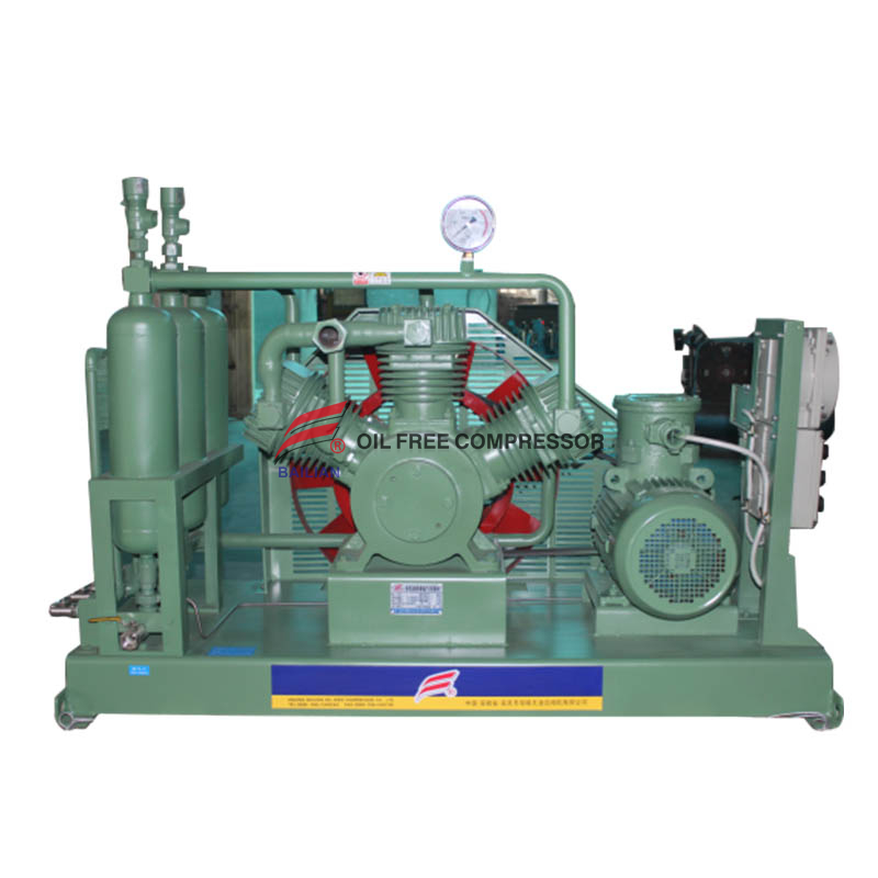
Engineering a hydrogen recycle compressor requires deep attention to specific failure modes. Hydrogen escapes easily, attacks steel at a molecular level, and heats up violently when compressed. You must address these three physical realities through rigorous design specifications and strict adherence to industry standards.
Managing low molecular weight gases requires advanced sealing systems. Technical trade-offs exist between mechanical packing rings for reciprocating units and tandem dry gas seals for centrifugal models. Reciprocating packing relies on a series of segmented rings that hug the piston rod. They always leak a small amount of gas by design. You must capture this leakage in a vent system and route it to the flare.
Centrifugal compressors utilize tandem dry gas seals. These non-contacting seals use spiral grooves etched into a rotating face to pump a microscopic film of gas against a stationary face. This creates a stiff gas bearing that prevents the faces from touching while blocking process gas escape. They are highly reliable but extremely sensitive to dirt and liquid contamination.
API Seal Piping Plans supply clean buffer gas. Plan 53B, Plan 54, and Plan 74 are common. Nitrogen typically isolates the process gas. You inject nitrogen between the primary and secondary seals. If the primary seal fails, the nitrogen blocks the hydrogen from reaching the atmosphere. Continuous monitoring of primary seal vent leakage ensures safe and compliant operation. A sudden spike in vent flow triggers an immediate trip.
Material selection is critical to mitigate hydrogen embrittlement. Wetted parts have strict metallurgical requirements. Hydrogen atoms are small enough to diffuse into the crystal lattice of steel. Once inside, they combine to form hydrogen gas molecules, creating massive internal pressure that rips the steel apart from the inside out. This causes sudden, catastrophic failure without warning.
Engineers must limit yield strength and avoid susceptible high-strength steels. Applying NACE MR0175 and ISO 15156 standards restricts carbon steel hardness to a maximum of 22 HRC (Rockwell C). This prevents hydrogen-induced cracking (HIC) in compressor valves, piston rods, cylinder liners, and high-speed impellers. You must specify post-weld heat treatment (PWHT) for all fabricated casings to relieve residual stresses.
Component | Recommended Material | Hardness Limit | Special Treatments |
|---|---|---|---|
Piston Rods | AISI 4140 Forged Steel | 22 HRC Max | Tungsten Carbide Coating |
Centrifugal Impellers | 17-4 PH Stainless Steel | 33 HRC Max (Specific NACE exception) | Double Overaged (H1150M) |
Cylinders / Casings | Carbon Steel (A516 Gr 70) | 22 HRC Max | 100% PWHT |
Valves | 316L Stainless Steel | 22 HRC Max | None |
Thermodynamic management dictates system longevity. Hydrogen features a high specific heat ratio ($C_p/C_v \approx 1.4$), causing rapid adiabatic temperature rise during compression. When you compress hydrogen, it gets hot very fast. If you try to achieve too high of a pressure ratio in a single stage, the gas temperature will exceed the mechanical limits of the compressor components.
Stage discharge temperatures must remain strictly capped below 135°C (275°F). Exceeding this limit causes seal degradation, oil carbonization, and structural weakening of the metal. Teflon rings in reciprocating compressors will melt and extrude if pushed past this temperature. You must design the machine with enough stages to keep the ratio per stage low.
Intercooler and aftercooler designs must maximize thermal transfer efficiency. Shell and tube heat exchangers are standard. The process gas typically flows through the tubes, while cooling water flows across the shell. You must size these coolers generously to account for fouling over time. Approach temperatures should be monitored daily by the operations team.
Capacity control provides necessary operational flexibility. Refineries rarely operate at a single, steady state. Feed rates change, catalyst activity declines, and ambient temperatures fluctuate. The compressor must adjust its throughput to match the process demand without wasting energy or venting gas to the flare.
Reciprocating units utilize step-less capacity control, clearance pockets, and bypass valves. Step-less systems use hydraulic actuators to hold the suction valves open for a portion of the compression stroke. This allows infinite control of the flow rate from 10% to 100%. Clearance pockets add dead volume to the cylinder, reducing volumetric efficiency and flow in fixed steps.
Centrifugal compressors rely on variable speed drives (VSD) and advanced surge control mechanisms. Changing the speed of the driver directly changes the aerodynamic performance of the impellers. Anti-surge valves protect the machine by recycling gas from the discharge back to the suction if the flow drops too low. These systems maintain stability in variable hydrogen-purity environments.
Deploying these massive machines involves significant engineering and operational risks. You must anticipate failure modes and design mitigation strategies into the initial project scope. Waiting until the machine is running to figure out maintenance procedures guarantees excessive downtime and lost production.
Understanding maintenance intervals improves reliability metrics. Reciprocating units commonly experience valve wear and rider band degradation. Valves are the beating heart of a reciprocating machine. They open and close millions of times a month. Springs break, plates crack, and seats wear out. You should plan for valve replacements every 8,000 to 12,000 hours of operation.
Centrifugal units face dry gas seal contamination and rotor dynamics issues. If liquid carryover hits a dry gas seal spinning at 20,000 RPM, the seal shatters instantly. You must maintain strict control over the buffer gas conditioning skid. Filters must be changed on schedule. Rotor dynamics issues, such as subsynchronous vibration, require specialized analysis to resolve.
Implementing condition-monitoring strategies transitions operations from reactive to predictive maintenance. Use vibration analysis, continuous temperature monitoring, and acoustic emission tracking. Acoustic sensors on reciprocating valves can detect a cracked plate days before it fails completely. Proximity probes on centrifugal shafts measure microscopic deflections in real-time.
Monitor primary seal vent flow daily; establish baseline and alarm limits.
Conduct monthly vibration spectrum analysis on all main bearings.
Track cylinder cooling water differential temperatures to detect fouling.
Analyze lube oil samples quarterly for wear metals and viscosity breakdown.
Perform acoustic emission testing on reciprocating valves every six months.
Compliance with API standards guarantees mechanical integrity. These standards represent decades of hard-learned lessons in the petrochemical industry. Adhering to API 618 manages pulsation, vibration, and mechanical design for reciprocating compressors. Pulsation dampeners (snubbers) must be acoustically modeled to ensure gas resonance does not shake the piping apart.
Applying API 617 ensures rotor stability, casing integrity, and dry gas seal reliability in barrel compressors. The standard dictates rigorous testing, including mechanical running tests and optional Type 1 or Type 2 aerodynamic performance tests. Strict adherence to these standards minimizes catastrophic failure risks. Never accept a machine that deviates from API requirements without a thoroughly documented engineering justification.
The optimal compressor design is never a universal standard. It remains a highly specific match to the refinery's flow rate, pressure ratio, and gas purity parameters. Specify reciprocating compressors for ultra-high pressure applications with variable capacity needs. Choose barrel-type centrifugal compressors for high-flow, continuous operations requiring maximum uptime. Proper material selection, advanced sealing, and strict thermodynamic management dictate the success of the installation.
Next Steps:
Conduct a comprehensive front-end engineering design (FEED) study to map specific process requirements and gas compositions.
Consult directly with OEM application engineers to verify aerodynamic performance maps and mechanical limits.
Review site-specific API data sheets thoroughly before initiating any procurement processes to ensure all NACE requirements are met.
Establish a predictive maintenance schedule utilizing continuous condition monitoring technologies prior to commissioning.
A: They feature a radially split casing design that eliminates the horizontal split-line. This provides superior containment and leak prevention for low-molecular-weight gases at extreme pressures. The single heavy end cover prevents casing distortion under high hydrocracking pressures.
A: Centrifugal units rely on tandem dry gas seals with nitrogen buffering. Reciprocating units use advanced polymer packing with purge chambers. Both require continuous API plan compliance, clean buffer gas supply, and strict vent monitoring to ensure safety.
A: It requires limiting material hardness and yield strength. Engineers must adhere to specific API and NACE MR0175 guidelines, keeping carbon steel hardness below 22 HRC, to prevent hydrogen-induced cracking and sudden mechanical failure of critical components.
A: API 617 governs centrifugal and axial compressors, focusing on rotor dynamics, aerodynamic performance, and casing design. API 618 governs reciprocating compressors, focusing on pulsation control, vibration limits, and valve reliability.
A: A drop in hydrogen purity increases the gas molecular weight. This shifts the compressor's operating point, potentially leading to surge or motor overload. It often requires immediate adjustments in speed and guide vane positioning to maintain stable operation.
A: They require frequent replacement intervals for compressor valves, piston rings, and rider bands. This wear occurs rapidly due to the non-lubricated or minimally lubricated environments typical in process gas recovery applications.
A: Hydrogen's thermodynamic properties cause high heat build-up during compression. Exceeding 135°C (275°F) significantly increases the risk of thermal expansion issues, seal breakdown, oil carbonization, and accelerated hydrogen embrittlement.