
- All
- Product Name
- Product Keyword
- Product Model
- Product Summary
- Product Description
- Multi Field Search

Views: 0 Author: Site Editor Publish Time: 2026-08-08 Origin: Site


Compressing high-purity oxygen is a high-stakes operation that demands uncompromising engineering. The combination of concentrated oxygen gas and elevated pressure creates a highly reactive environment where even microscopic hydrocarbon contaminants can trigger catastrophic combustion. System cleanliness and precise thermal management are absolute necessities for facility survival. When primary oxygen generation systems, such as low-pressure Pressure Swing Adsorption (PSA) plants, fail to deliver the discharge pressure required by downstream applications, operations face severe bottlenecks. This pressure deficit leads to unstable gas delivery, interrupted cylinder filling, and costly process downtime in critical medical or industrial applications.
The solution lies in integrating a purpose-built Oxygen Booster Compressor. This specialized equipment acts as the critical bridge between low-pressure generation and high-pressure utilization. Proper design selection dictates operational safety, eliminates ignition risks, and ensures long-term mechanical reliability under continuous load.
Strict Oil-Free Mandate: High-pressure oxygen compression requires rigorously engineered oil-free or diaphragm architectures to eliminate hydrocarbon ignition risks.
System Synergy: A properly sized PSA oxygen booster must match the output flow, dew point, and inlet pressure of the primary generator to prevent cavitation, system starvation, or seal degradation.
Thermal Management is Critical: The adiabatic heat generated during compression must be aggressively managed through multi-stage cooling to maintain structural integrity and safety.
Understanding gas delivery requires defining the baseline difference between primary and secondary compression. A primary compressor draws atmospheric air, which contains roughly 21% oxygen, and compresses it to a low or moderate pressure to feed a separation system. In contrast, an oxygen booster compressor receives pre-purified, pre-compressed oxygen gas and elevates it to extreme high-pressure levels required for storage or specialized usage. You cannot use standard air compressors for this task; the internal mechanics and materials are fundamentally different.
Facilities frequently encounter a significant pressure gap. A standard oxygen generator typically discharges gas at 4 to 6 bar (60 to 90 psi). However, standard cylinder storage requires 150 to 200 bar (2,100 to 2,900 psi). Specialized industrial and aerospace applications demand even higher thresholds, sometimes reaching up to 2,690 bar (39,000 psi). Bridging this gap safely requires equipment specifically engineered for the reactive nature of pure oxygen. We see many operations struggle because they underestimate the mechanical strain of boosting gas across such a wide pressure differential.
The operational dynamics between a separation plant and a PSA oxygen booster require precise synchronization. PSA technology operates on a cyclical basis, alternating between adsorption and desorption phases. This creates inherent pressure and flow fluctuations at the discharge point. Direct-feeding a booster from a PSA outlet without conditioning the flow leads to erratic suction pressures and mechanical stress on the compressor valves.
Surge tanks or buffer vessels must be installed between the generator and the booster. These vessels act as pneumatic shock absorbers, smoothing out cyclical fluctuations and providing a steady, consistent inlet pressure. The primary-to-booster handoff is a critical engineering calculation. The discharge flow of the generator must perfectly match or slightly exceed the inlet suction limits of the booster. If the booster draws more gas than the generator produces, it creates a vacuum condition, leading to system starvation, overheating, and rapid seal degradation. Field installations often fail because the buffer tank is undersized, causing the booster to short-cycle and destroy its internal seals prematurely.
Reliable high pressure oxygen compression serves several critical sectors. Medical gas pipelines rely on these systems to maintain continuous facility pressure, while emergency and portable cylinder filling stations use them to stockpile life-saving respiratory gas. In these environments, equipment failure directly impacts patient care, making redundancy and reliability paramount.
Industrial applications consume massive volumes of pressurized oxygen. Metal cutting, heavy welding, and laser cutting processes use high-pressure oxygen as an assist gas to blow away molten slag and accelerate the oxidation of the metal, resulting in clean, rapid cuts. Chemical oxidation processes also depend on stable, high-pressure delivery to maintain reaction kinetics. If the pressure drops during a laser cutting operation, the cut quality degrades instantly, ruining expensive raw materials.
Aerospace, aviation, and deep-sea diving represent the most demanding applications. These life-support systems require certified ultra-high purity gas. Any particulate shedding or contamination introduced during the compression phase can compromise life-support equipment or cause catastrophic failures in oxygen-rich environments. The tolerances here leave zero room for error.
Selecting the right architecture depends entirely on required flow rates, target discharge pressures, and duty cycles. Matching the mechanical design to the operational reality prevents premature equipment failure. We evaluate three primary designs in the field.
Reciprocating compressors use pistons driven by a crankshaft to compress gas within cylinders. For oxygen service, these must be strictly oil-free. They utilize PTFE or specially formulated non-lubricated piston rings and rider bands that operate without any liquid lubrication. This eliminates the hydrocarbon fuel source required for an oxygen fire. The crankcase may contain oil, but it is physically separated from the compression cylinders by an extended distance piece and oil wiper rings.
These units excel in high-flow, continuous-duty industrial applications where massive volumes of gas must be moved efficiently. However, the dry-running nature of the seals introduces trade-offs. The mechanical friction causes higher wear on the piston rings, requiring strict, frequent maintenance intervals. Additionally, the wearing of these non-metallic rings can cause particulate shedding, necessitating robust downstream filtration to protect sensitive end-use equipment. You must plan for regular downtime to replace these wear parts.
Diaphragm compressors utilize a flexible metallic membrane to completely isolate the oxygen gas from all moving mechanical parts and hydraulic drive fluids. The piston moves hydraulic fluid, which in turn flexes the diaphragm, compressing the gas in a hermetically sealed cavity. The gas only touches the metal diaphragm and the static head of the compressor.
This architecture is the absolute standard for ultra-high purity requirements and extreme high-pressure applications. Because the gas never contacts wearing seals or lubricants, there is zero risk of cross-contamination or particulate shedding. They can safely achieve pressures up to 2,690 bar (39,000 psi). The trade-offs include a significantly higher capital cost, a larger physical footprint, and lower volumetric flow rates compared to reciprocating models. When purity is the only metric that matters, this is the required choice.
Pneumatic gas boosters utilize compressed shop air or nitrogen to drive a large-area piston, which is mechanically linked to a smaller-area high-pressure piston. This differential area principle allows low-pressure drive air to generate exceptionally high gas pressures. They are available in single-stage or double-acting configurations.
These units are best suited for intermittent duty, portable cylinder filling, and hazardous environments. Because they are entirely air-driven, they require no electrical power, making them inherently spark-free and safe for explosive atmospheres. However, they are highly inefficient for continuous, high-volume production due to their massive drive-air consumption rates. Running a pneumatic booster 24/7 will quickly drain your facility's compressed air capacity.
Compressor Type | Primary Mechanism | Best Application | Key Limitation |
|---|---|---|---|
Oil-Free Reciprocating | Dry PTFE piston rings | High-flow, continuous industrial use | Seal wear and particulate shedding |
Diaphragm | Flexible metal membrane isolation | Ultra-high purity, extreme pressure | Lower flow rates, larger footprint |
Pneumatic Air-Driven | Differential area piston | Intermittent use, hazardous locations | High drive-air consumption |
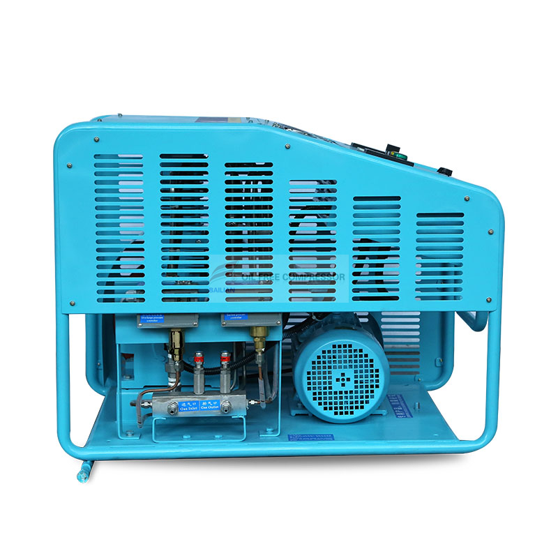
Translating manufacturer specification sheets into real-world operational outcomes requires evaluating the engineering behind the components. Surface-level specifications often hide critical operational limitations that only become apparent after installation.
Standard carbon steel and aluminum are highly susceptible to oxidation and can act as fuel in high-pressure oxygen environments. Oxygen-compatible metallurgy is mandatory. Components in the wetted gas path must be machined from Monel, specific grades of brass, bronze, or specialized stainless steels to prevent oxidation, sparking, and ignition. Using the wrong metal in a high-velocity gas stream is a guaranteed failure point.
Furthermore, the equipment must adhere to strict oxygen clean standards, such as ASTM G93 or CGA G-4.1. This cleaning process removes all trace hydrocarbons, machining oils, and particulates. Verifying a manufacturer's cleaning certification is a non-negotiable safety requirement. Utilizing standard gas boosters designed for nitrogen or helium interchangeably for oxygen service invites disaster. Even if a standard booster is cleaned, its internal metallurgy may not be oxygen-compatible, presenting a severe ignition risk.
Compressing gas generates adiabatic heat. In an oxygen system, unmanaged heat rapidly approaches the auto-ignition temperature of internal non-metallic components. Aggressive thermal management is critical to keep the equipment from destroying itself.
Systems are typically air-cooled or water-cooled. Air-cooled systems rely on ambient facility temperatures; if the compressor room exceeds optimal thresholds, the unit will overheat and shut down. Water-cooled systems provide superior heat dissipation for continuous duty requirements. Multi-stage booster designs must incorporate highly efficient inter-stage and after-coolers to strip heat from the gas between compression cycles, ensuring the discharge temperature remains well below ignition thresholds.
Cooling Method | Infrastructure Required | Ideal Operating Environment | Maintenance Focus |
|---|---|---|---|
Air-Cooled | High-volume ventilation fans | Climate-controlled or cool ambient rooms | Cleaning cooling fins and fan blades |
Water-Cooled | Chiller loop or municipal water tie-in | Hot environments, continuous heavy duty | Monitoring water quality and scale buildup |
The compression ratio dictates how much heat is generated per stage. Exceeding a 4:1 compression ratio per stage in oxygen service is generally avoided. Pushing a single stage beyond this limit generates excessive adiabatic heat that cooling systems cannot effectively manage. Multi-stage designs distribute the workload and the heat generation across several cylinders.
Variable frequency drives (VFDs) offer significant advantages for matching booster output to fluctuating downstream demand. Instead of the compressor rapidly cycling on and off—which causes severe mechanical fatigue on the motor and valves—a VFD adjusts the motor speed to maintain a stable, continuous flow rate that matches the exact consumption of the facility. This extends the life of the equipment dramatically.
The quality of the gas entering the booster directly impacts seal life and overall reliability. High inlet moisture (a poor dew point) causes condensation within the compression cylinders. This moisture accelerates the wear of PTFE rings and can cause internal corrosion, leading to premature failure.
Particulate filtration is equally critical. Abrasive dust from a PSA generator will destroy non-metallic seals in hours. Inlet filters protect the internal components from abrasive wear and prevent the generation of static sparks caused by high-velocity particulate impacts within the valve assemblies. We always mandate dual-stage filtration on the inlet side to protect the compressor investment.
Installing high-pressure gas systems introduces hidden challenges. Robust safety instrumentation and strict maintenance protocols separate reliable facilities from hazardous ones. You cannot cut corners on safety controls when dealing with pure oxygen.
Manual monitoring is insufficient for high-pressure oxygen. Systems require automated, redundant safety controls. High-temperature automatic shutdown sensors must be installed on the discharge of every stage to instantly cut power if thermal runaway occurs. By the time an operator notices a temperature spike, the internal damage is already done.
Low inlet pressure switches protect the compressor from starvation. If the primary generator fails, the switch prevents the booster from pulling a vacuum, which could draw atmospheric contaminants into the system. High discharge pressure relief valves and mechanical burst discs provide the final line of defense against catastrophic over-pressurization, venting gas safely if electronic controls fail.
Physical installation requires planning for the booster, buffer tanks, and mandatory safety clearance zones. High-pressure oxygen systems cannot be crammed into unventilated utility closets. Operators must evaluate electrical load requirements for high-horsepower electric motors to ensure the facility grid can handle the startup amperage without tripping breakers.
For pneumatic systems, the capacity of the existing shop air infrastructure must be audited. Pneumatic boosters consume massive volumes of drive air; an undersized shop air compressor will cause the oxygen booster to stall, halting production entirely.
Manufacturer claims regarding maintenance intervals must be scrutinized against actual duty cycles. Continuous operation at maximum discharge pressure accelerates wear significantly compared to intermittent use. You must plan maintenance based on your specific operational load, not just the manual's best-case scenario.
The most common failure points are high-pressure piston seals, check valves, and diaphragm membranes. Operators must account for the procurement lead times of specialized, oxygen-compatible replacement parts. Stocking critical spares on-site prevents minor seal failures from causing week-long production halts.
Compliance with industry standards is not optional. Medical applications must adhere to ISO 13485 for medical devices. Industrial systems must comply with the ASME Boiler and Pressure Vessel Code for receiver tanks and CGA (Compressed Gas Association) guidelines for safe handling.
Utilizing non-certified equipment for oxygen service carries massive liability risks. If an incident occurs with uncertified equipment, facility managers face severe legal and regulatory consequences. Always demand full material test reports and cleaning certificates before commissioning a new system.
There is no universal oxygen booster compressor. The optimal choice is strictly dictated by the intersection of purity needs, pressure targets, safety certifications, and duty cycle. Misapplying a compressor architecture leads to rapid mechanical failure and severe safety hazards. You must match the machine to the exact demands of your facility.
When selecting equipment, apply strict shortlisting logic. Choose pneumatic boosters exclusively for low-volume, intermittent cylinder filling or operation in hazardous, spark-free locations. Select oil-free reciprocating boosters for high-volume, continuous industrial flow and standard cylinder filling applications where scheduled maintenance is acceptable. Specify diaphragm compressors for ultra-high purity requirements, zero-leakage mandates, and extreme high-pressure applications.
To move forward effectively, take the following actions:
Audit current primary oxygen output, recording exact flow rates, discharge pressure, and dew point.
Define precise downstream requirements, including peak consumption rates and minimum acceptable pressure.
Request detailed maintenance schedules and oxygen-cleaning material certifications from all shortlisted vendors before final selection.
Evaluate your facility's cooling capacity and electrical infrastructure to ensure compatibility with the chosen compressor architecture.
A: While standard cylinder filling typically requires 150 to 200 bar (2,100 to 2,900 psi), specialized diaphragm boosters can safely achieve extreme pressures exceeding 2,690 bar (39,000 psi) for specific aerospace and industrial applications.
A: High-pressure oxygen combined with hydrocarbon-based lubricants completes the combustion triangle. This combination creates an immediate, highly volatile, and severe explosion hazard inside the compression cylinder.
A: A PSA oxygen booster features specific oxygen-compatible metallurgy, undergoes specialized oxygen-cleaning processes to remove all hydrocarbons, and utilizes stringent thermal management systems to prevent adiabatic ignition.
A: No. Even if cleaned to ASTM G93 standards, standard gas boosters often contain incompatible internal materials like standard carbon steel that oxidize rapidly and pose a severe spark and safety hazard.
A: Maintenance depends heavily on the architecture and duty cycle. Oil-free piston seals typically require replacement every 2,000 to 4,000 operating hours, whereas diaphragm compressors generally offer longer intervals between major overhauls.
A: While technically possible, it is highly inefficient and expensive for continuous duty due to the massive volume of compressed drive-air required to keep the booster running. They are optimized for intermittent use.
A: Ignition is prevented by utilizing multi-stage compression to keep pressure ratios low per stage, combined with aggressive inter-stage cooling and automated temperature transmitters that shut the system down if heat exceeds safe limits.