
- All
- Product Name
- Product Keyword
- Product Model
- Product Summary
- Product Description
- Multi Field Search

Views: 0 Author: Site Editor Publish Time: 2026-08-08 Origin: Site


Compressing oxygen introduces unique thermodynamic and safety challenges. These severe risks do not exist for inert gases or standard shop air. When you compress any gas, its internal temperature rises rapidly. Pushing for the highest possible compression ratio often leads to excessive adiabatic heating. This intense heat directly accelerates internal seal wear. It also dramatically increases ignition risks in an oxygen-rich environment. Facility engineers and procurement teams frequently evaluate an Oxygen Booster Compressor for their industrial operations. Determining the "practical" compression ratio is absolutely critical. You must carefully balance daily operational efficiency, long-term equipment lifespan, and strict safety compliance. Ignoring these variables invites catastrophic equipment failure. In this comprehensive guide, you will learn how to identify safe compression limits. We will explore how your specific gas source dictates internal staging configurations. We will also discuss key evaluation criteria to help you select a highly reliable and safe system.
Rapid gas compression generates immense thermal energy. This physical principle is commonly known as adiabatic heating. Inert gases handle this rapid heat generation relatively well. Pure oxygen behaves very differently under mechanical stress. In an oxygen-enriched environment, heat acts as the primary catalyst for system failure. High temperatures significantly lower the ignition threshold of surrounding materials. Even minimal friction from internal moving parts can cause catastrophic combustion. You must control internal temperatures strictly during high pressure oxygen compression.
Industry standards prioritize facility safety above all else. Frameworks like ASTM G88 guidelines rigorously govern oxygen system design. They generally restrict single-stage compression ratios to a strict 4:1 to 6:1 window. Staying within this specific range keeps discharge temperatures manageable. Pushing beyond a 6:1 ratio in one stage invites dangerous thermal spikes. It severely stresses the physical boundaries of the internal metals and polymers.
Some plant operators desire much smaller equipment footprints. They might push vendors for higher single-stage compression ratios. Higher ratios mean you need fewer internal compression stages. This choice undeniably reduces initial equipment size and physical weight. However, it creates severe mechanical trade-offs. You will suddenly demand aggressive, complex external cooling systems. You will also rely heavily on highly specialized seal materials like glass-filled PTFE. These advanced seals degrade much faster under intense thermal loads. We strongly recommend prioritizing thermal safety over a smaller physical footprint. A larger, multi-stage machine runs cooler and lasts much longer.
Material selection plays a massive role in thermal management. Standard carbon steel rusts and burns easily in pure oxygen. Engineers must use specialized metals like Monel, bronze, or aerospace-grade brass for internal cylinders. These materials resist ignition even when adiabatic heating pushes temperatures upward. Respecting the 6:1 compression limit ensures these specialized metals remain structurally intact.
Your inlet gas source completely dictates your ideal compression ratio. Different industrial gas sources provide very different starting pressures. We must evaluate two common industrial scenarios to understand proper system sizing.
First, consider the process of integrating a pressure swing adsorption system. Pressure Swing Adsorption (PSA) generators typically output very low pressures. You might start with a baseline of 40 to 90 PSI. Many medical or industrial applications require filling storage cylinders to 2,200 PSI. A single compression stage absolutely cannot safely achieve this massive jump. The required overall ratio approaches 30:1 or more in this scenario. You must use a two-stage or three-stage booster configuration. Multi-stage designs easily maintain safe inter-stage temperatures. They effectively cool the gas between each sequential compression cycle. This sequential cooling prevents the final discharge temperature from reaching dangerous ignition thresholds.
Next, consider scavenging oxygen from high-pressure cylinders or liquid dewars. Facilities often vaporize liquid oxygen to create a pressurized gas supply. These robust sources often supply a starting inlet pressure between 300 and 500 PSI. Boosting this pre-pressurized gas up to 3,000 PSI is much easier. The overall pressure ratio remains relatively low across the entire system. You can often achieve this target using a robust single-stage booster. The internal compression ratio stays safely under the critical 6:1 limit. This streamlined setup requires fewer moving parts and simplifies your preventative maintenance routine.
You must also carefully evaluate volumetric flow alongside your compression ratio. Operators often want maximum gas delivery speeds. Prioritizing high flow rates at maximum compression ratios causes significant mechanical problems. It rapidly increases physical wear on dynamic piston seals. It also damages internal check valves due to extreme gas velocity. Moving large volumes of gas quickly generates immense extra friction. You should always balance your desired flow rate against safe compression limits. Slowing the compressor down often increases overall lifespan. Standardizing on a slightly lower flow rate reduces heat and extends operational periods between rebuilds.
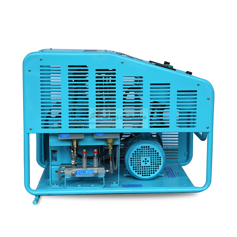
Decision makers face several highly technical choices during equipment procurement. Evaluating cooling mechanisms is a critical first step. You generally choose between standard air-cooled and advanced water-jacketed systems. Water cooling removes heat much more effectively from metal cylinders. This thermal efficiency allows for slightly higher practical compression ratios. However, water-jacketed systems dramatically increase overall installation complexity. You need dedicated plumbing infrastructure and a continuous clean water supply. Air-cooled systems remain simpler to install but handle significantly less heat. They rely entirely on ambient air temperature and external cooling fins.
Next, you must evaluate the primary drive type. Compressors typically use either pneumatic or electric drive motors. Air-driven boosters work exceptionally well for variable compression ratios. They naturally stall safely when they reach their maximum set pressure. They also require less complex facility infrastructure. However, they consume large volumes of shop compressed air to drive the internal pistons.
Electric-driven systems fit entirely different operational profiles. They excel in continuous, high-volume production operations. They maintain strictly defined compression ratios without relying on external shop air. Electric units provide consistent power delivery. They also require sophisticated electrical control panels for safe and precise operation.
Finally, strict oxygen-clean compliance remains completely non-negotiable. Every internal component must be meticulously built, cleaned, and certified for oxygen service. Do not ever trust standard industrial air compressors for pure oxygen duty. Residual machining oils and hydrocarbons will ignite instantly under high pressure. Ensure your chosen vendor provides comprehensive oxygen-cleaning documentation. They must follow established cleaning protocols like CGA G-4.1. Technicians must inspect every part under UV black light to verify total hydrocarbon removal.
Compressor Drive Type Comparison
| Drive Type | Ideal Application | Key Advantage | Primary Limitation |
|---|---|---|---|
| Pneumatic (Air-Driven) | Variable ratio operations | Inherently stall-safe design | Requires massive shop air supply |
| Electric-Driven | Continuous high-volume duty | Consistent flow and defined ratios | Requires heavy electrical infrastructure |
| Hydraulic-Driven | Ultra-high pressure applications | Smooth, slow piston stroke | High system weight and complexity |
Running any high-pressure compression system involves inherent operational risks. Inlet pressure drops create severe and sudden mechanical hazards. Imagine your primary gas generator suddenly loses operational efficiency. Your critical inlet supply pressure dips unexpectedly during a busy shift. The compressor still attempts to reach the same final discharge pressure. This scenario causes the internal compression ratio to spike artificially. Sudden ratio spikes lead directly to immediate equipment overheating. You must install redundant low-inlet-pressure shutdown switches. These simple safety devices reliably prevent dangerous thermal runaway events.
Seal degradation cycles present another major daily reality. We can make a transparent assumption about preventative maintenance schedules. Running a booster at the absolute maximum of its designed ratio accelerates physical wear. You might cut your routine seal replacement interval by up to 50 percent. Intense concentrated heat hardens and degrades even the best specialized oxygen seals. Operating closer to a conservative 4:1 ratio significantly extends seal life. It drastically reduces unexpected downtime for your facility.
Filtration and contamination risks also multiply rapidly at high ratios. Multi-stage systems face constant hydrocarbon migration threats. Even microscopic trace amounts of grease can trigger the "diesel effect." This phenomenon occurs when compression heat ignites trapped hydrocarbons. You must implement rigorous multi-tier filtration at the gas inlet. Regular visual filter inspections prevent contaminants from entering the main compression chamber. A tiny particle of dirt moving at high velocity creates friction sparks. In pure oxygen, a single spark destroys the entire machine instantly.
Common maintenance mistakes include using standard tools to service oxygen equipment. Mechanics must use dedicated, oil-free tools. Cross-contamination from a greasy wrench ruins the oxygen-clean status of the entire compressor. Always maintain a sterile environment when replacing internal seals or checking internal valves.
Selecting the correct mechanical hardware requires a highly systematic approach. Follow these clear, actionable steps to shortlist appropriate manufacturing vendors.
Before making a final purchase, consider requesting real-world references. Speak to other plant engineers running similar compression ratios. Ask them about their actual seal replacement intervals. Real-world maintenance data reveals the truth behind theoretical compression limits. A reliable vendor openly shares both engineering successes and mechanical limitations.
A highly practical compression ratio achieves your target pressure effortlessly. It does this without triggering dangerous thermal hazards or excessive mechanical downtime. You must balance your flow requirements against thermodynamic realities. Pushing single-stage ratios past safe limits guarantees premature equipment failure.
Technical buyers should stop looking exclusively at maximum theoretical ratios. Instead, we strongly advise requesting detailed inter-stage temperature calculations from potential vendors. Base these technical requests on your specific facility inlet conditions. Understanding heat generation ensures long-term operational success.
Your safety and production uptime depend on accurate system sizing. Do not risk your facility by guessing compression limits or ignoring safety protocols. We prompt you to consult directly with our experienced engineering team. We provide custom system sizing and rigorous safety evaluations for your specific application.
A: In a single stage, no. It poses severe thermal risks. Pushing a 10:1 ratio generates heat well beyond safe ignition thresholds for oxygen. An overall 10:1 ratio is easily and safely achieved using a two-stage booster system with inter-cooling.
A: Usually, this is caused by the inlet pressure from the PSA dropping below the booster’s minimum requirement. This sudden drop forces the booster to operate at an unsafely high compression ratio. Installing low-pressure shutdown switches prevents this specific thermal issue.
A: Not necessarily. Flow rate (displacement) determines your overall filling speed, while the compression ratio determines the final pressure capability. Pushing the ratio too high can actually reduce efficiency due to volumetric losses and excessive heat.