
- All
- Product Name
- Product Keyword
- Product Model
- Product Summary
- Product Description
- Multi Field Search

Views: 0 Author: Site Editor Publish Time: 2026-08-12 Origin: Site


Carbon dioxide presents a unique thermodynamic challenge in industrial facilities. Unlike standard air or natural gas, CO2 undergoes significant phase changes—shifting between gas, liquid, and supercritical states—depending on precise temperature and pressure variables. This volatility makes sizing a CO2 Compressor a high-stakes engineering endeavor. Miscalculating the required pressure range carries substantial financial and operational risks. Over-pressurizing leads to exponential energy waste and unnecessary capital expenditure, while under-pressurizing causes pipeline phase-separation, transport failures, or rejected geological injection.
Determining the correct pressure range requires working backward from the final application—whether that is liquefaction, pipeline transport, or enhanced oil recovery—to the inlet source. This reverse-engineering approach establishes the foundational criteria for specifying an industrial CO2 compression system that operates efficiently and safely on the plant floor.
Application Dictates Pressure: Required discharge pressures vary drastically, from 10–15 bar (145–220 psi) for local liquefaction and storage, to 1,500–2,200 psi for long-distance pipeline transport and geological re-injection.
Inlet Conditions Matter: System design must account for inlet pressures that can range from near-atmospheric (3 psig) in post-combustion capture to 500 psia in pre-combustion scrubbing, heavily influenced by upstream stripper and reboiler utility limits.
Purity is Non-Negotiable: For food, beverage, and specific chemical applications, utilizing an oil free carbon dioxide compressor is mandatory to prevent downstream contamination and meet compliance standards.
Thermodynamic Management: Managing the heat of compression through multi-stage intercooling is critical to maintaining efficiency and preventing CO2 from reaching supercritical states prematurely.
The primary success criterion for CO2 compression is maintaining the fluid in the correct phase—typically dense phase or supercritical—to ensure efficient transport and storage without damaging the compressor internals. The thermodynamic threshold of CO2, known as the critical point, occurs at approximately 1,070 psi (73.8 bar) and 87.8°F (31°C). Crossing into the supercritical phase alters fluid density and viscosity significantly. These changes directly impact compressor aerodynamics, seal design, and power requirements. Field operators must monitor these parameters constantly to avoid catastrophic equipment failure.
Operating near 800 psi at room temperature (70–80°F) introduces specific risks. At this state, CO2 becomes a highly volatile dense gas/liquid transitional mixture. This transitional phase demands precise system controls compared to managing a fully saturated liquid, which typically requires pressures between 860 and 975 psig. When designing the piping layout, engineers must account for sudden pressure drops that can cause dry ice formation, blocking valves and damaging impellers. Proper insulation and heat tracing along the suction lines prevent these unwanted phase shifts before the gas enters the first compression stage.
To manage these phase behaviors, operators rely on robust instrumentation. Pressure transmitters and temperature sensors feed data back to the main control panel, allowing the system to adjust bypass valves and cooling water flow rates dynamically. If the gas temperature rises too quickly during compression, the density drops, reducing the mass flow rate and forcing the compressor to work harder. This is why interstage cooling is not just an efficiency measure; it is a fundamental requirement for keeping the CO2 within the safe operating envelope of the machine.
Furthermore, the specific heat ratio of CO2 changes as it approaches the critical point. This non-linear behavior means that standard ideal gas calculations fall short. Compressor manufacturers use complex equations of state, like Peng-Robinson or Span-Wagner, to predict the exact volume and temperature at each stage. When you are on site commissioning a new unit, you will often see discrepancies between theoretical models and actual performance if the gas composition varies even slightly, such as having trace amounts of nitrogen or methane mixed with the CO2.
Here are the primary checks operators perform to verify phase stability during startup:
Verify inlet gas temperature is at least 10°F above the dew point to prevent liquid slugging.
Confirm interstage cooler outlet temperatures remain below 90°F.
Check separator liquid levels to ensure moisture is draining properly before the next stage.
Monitor vibration levels on the compressor frame, as phase changes can cause severe mechanical imbalance.
Inspect blowdown valves for frost accumulation, indicating localized pressure drops and potential dry ice formation.
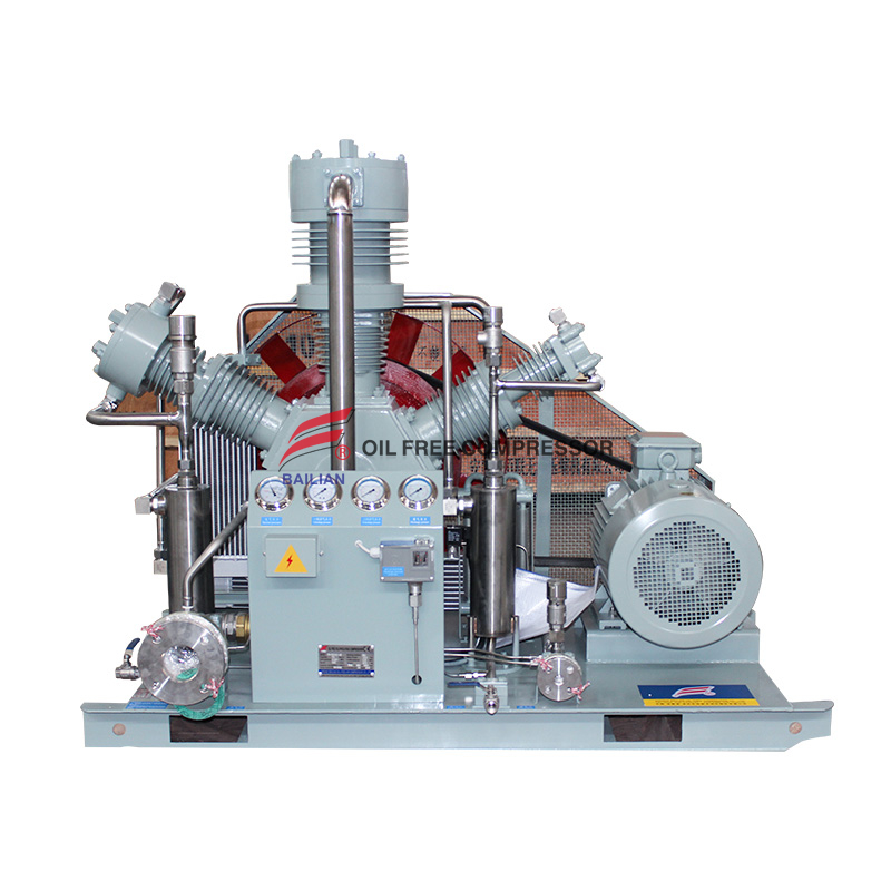
For the food and beverage industry, localized industrial storage, and cryogenic transport, the target pressure range is typically 10 to 15 bar (approximately 145 to 220 psi). The primary evaluation dimension here is temperature control. CO2 must be cooled significantly to remain liquid at these lower pressures. This contrasts with small-scale recovery systems that operate at 800 to 975 psig for ambient-temperature liquid storage. In breweries and bottling plants, the gas is often recovered directly from fermentation tanks, requiring careful scrubbing and compression to meet strict food-grade standards.
Maintaining this 10 to 15 bar range requires a dedicated refrigeration loop, usually utilizing ammonia or freon, to chill the CO2 down to -20°F (-29°C). The compressor itself is usually a two-stage reciprocating or rotary screw design. Operators must ensure that the lubrication system, if present, does not leak into the gas stream. This is why many facilities opt for an oil free carbon dioxide compressor to eliminate the risk of contaminating the final product. Regular maintenance involves checking the PTFE rider bands and piston rings for wear, as they degrade faster without oil lubrication.
Mid-scale Carbon Capture, Utilization, and Storage (CCUS) networks and regional distribution systems generally operate in the 70 to 90 bar range (approximately 1,000 to 1,300 psi). System designers must balance pipeline material costs, specifically wall thickness, against compressor energy consumption as the fluid approaches the critical point. At 90 bar, the CO2 is typically in a dense phase, which is highly efficient for pipeline transport because it behaves more like a liquid, reducing the friction losses associated with gas transport.
Pumping CO2 at these pressures requires heavy-duty multi-stage compressors. The piping infrastructure must be built from high-grade carbon steel or stainless steel, depending on the moisture content. If the CO2 is completely dry, standard carbon steel is sufficient. However, any upset condition that introduces water will immediately form carbonic acid, eating through carbon steel pipes in a matter of weeks. Therefore, the compression facility must include a robust dehydration unit, usually a Triethylene Glycol (TEG) contactor, located between the intermediate compression stages.
Deep saline aquifer storage, Enhanced Oil Recovery (EOR), and massive-scale carbon sequestration require target ranges of 1,500 to 2,200 psia. This high pressure is critical for coal flue gas or synthesis gas capture applications. Operating well above the critical pressure ensures the CO2 remains in a dense, supercritical phase, preventing two-phase flow which can cause pipeline cavitation and severe pressure drops. When injecting into geological formations, the pressure must overcome the natural reservoir pressure, which increases significantly with depth.
These massive installations rely on integrally geared centrifugal compressors or massive API 618 reciprocating units. The foundation design for these machines is a major civil engineering task. A 10,000 horsepower reciprocating compressor generates immense dynamic forces. The concrete block must be isolated from the surrounding plant structure to prevent vibration transmission. On the process side, the gas must be cooled after every single stage. A typical six-stage compressor will have six massive shell-and-tube heat exchangers, requiring a dedicated cooling water tower just to handle the heat of compression.
Offshore Floating Production Storage and Offloading (FPSO) operations, high-flow marine injection, and advanced chemical synthesis demand extreme pressures. Discharge pressures can reach up to 540 bar (approximately 7,800 psi), with design pressures up to 670 bar. These applications involve extreme engineering requirements, including API 6A (10,000 psi) compliance, API 618/617 structural standards, advanced pulsation dampening, and "three-point" base-plate designs to isolate the compressor skid from offshore hull deflections.
Working on an FPSO introduces space and weight limitations. The compressor packages must be highly compact. Maintenance access is notoriously difficult, meaning reliability is paramount. The pulsation dampeners (snubbers) must be acoustically tuned to prevent standing waves in the high-pressure piping, which could literally shake the piping off its supports. The materials used for the compressor valves and cylinder heads are often specialized alloys like Inconel or Super Duplex stainless steel to withstand both the extreme pressure and the corrosive marine environment.
Application | Target Pressure Range | Phase State | Typical Compressor Type |
|---|---|---|---|
Liquefaction & Storage | 10 - 15 bar (145 - 220 psi) | Cold Liquid | Rotary Screw / Reciprocating |
Regional Pipeline | 70 - 90 bar (1,000 - 1,300 psi) | Dense Phase | Centrifugal / Reciprocating |
Geological Re-injection | 1,500 - 2,200 psia | Supercritical | Multi-stage Centrifugal / API 618 |
Marine / FPSO Injection | Up to 540 bar (7,800 psi) | Supercritical | High-Pressure Reciprocating |
The starting pressure dictates the required compression ratio and the number of stages needed. Inlet conditions connect directly to upstream thermal regeneration processes. For example, stripper and reboiler operating conditions, such as using low-pressure steam at 302°F (150°C) and 58 psia (4 bar), influence the CO2 product pressure entering the compressor inlet, which can be as low as 3 psig. Post-combustion capture often starts near atmospheric pressure, contrasting sharply with pre-combustion scrubbing or industrial synthesis gas purification, where inlet pressures range from 20 to 500 psia.
When dealing with atmospheric inlet pressures, the first stage cylinders of a reciprocating compressor must be massive to handle the high volumetric flow rate. As the gas is compressed and cooled, its volume shrinks dramatically, meaning subsequent cylinders get progressively smaller. If the inlet pressure fluctuates, it throws off the balance of the entire machine. Operators must install suction pressure control valves and recycle loops to maintain a constant inlet pressure, ensuring the compressor does not trip on low suction pressure or overload the motor during high-pressure spikes.
Sensitive applications necessitate an oil-free system. Comparing dry-running compressors—which utilize PTFE rings and labyrinth seals—against oil-flooded alternatives reveals significant operational differences. Oil carryover can foul catalysts in chemical plants or violate FDA and EFSA standards in food-grade applications, making oil-free designs essential. Even a few parts per million of lubricating oil can ruin a batch of beverage-grade CO2 or poison the expensive catalysts used in methanol synthesis.
In a dry-running CO2 compressor, the distance piece—the section between the gas cylinder and the crankcase—is critical. It prevents oil from migrating up the piston rod and entering the gas stream. For highly sensitive applications, double-compartment distance pieces are used, often purged with inert nitrogen to create a positive barrier. Maintenance teams must regularly inspect the oil wiper rings and rod packing. If the packing fails, gas leaks out, and oil creeps in. Monitoring the vent lines from the distance piece provides early warning of packing degradation.
The presence of free water combined with CO2 creates highly corrosive carbonic acid. Evaluating the need for upstream dehydration units, such as TEG contactors or molecular sieves, is crucial. Additionally, specifying stainless steel internals for the first compression stages is necessary, as this is where condensation is most likely to occur. When hot, wet CO2 from a capture plant hits the first intercooler, water drops out rapidly. The knockout drums must be sized correctly to handle this liquid volume.
If the knockout drum auto-drain fails, water will carry over into the next compression stage. Liquids are incompressible. If water enters a reciprocating compressor cylinder, it will blow the cylinder head off or bend the piston rod—a catastrophic failure known as hydro-locking. Therefore, redundant level transmitters and high-level shutdown switches are mandatory on all interstage separators. Furthermore, the piping from the cooler to the separator should be sloped to ensure gravity assists the liquid drainage.
These units provide high-volume, multi-stage dynamic compression. They are ideal for large-scale industrial CO2 compression applications like CCUS and pipelines requiring high flow rates and discharge pressures up to 200+ bar. They have a narrower operating envelope, making them susceptible to surge if process conditions fluctuate. Surge occurs when the discharge pressure exceeds the compressor's ability to push the gas forward, causing a violent flow reversal that can destroy the impellers and bearings in seconds.
To prevent surge, centrifugal compressors rely on complex anti-surge control systems. These systems continuously calculate the operating point relative to the surge line and open a recycle valve to maintain minimum flow through the machine. Because CO2 has a high molecular weight, the aerodynamic forces inside the casing are immense. The impellers are typically milled from solid blocks of high-strength steel or titanium. The gearboxes driving these impellers operate at extremely high speeds, often exceeding 20,000 RPM, requiring specialized hydrodynamic bearings and forced-feed lubrication systems.
Reciprocating compressors utilize positive displacement compression. They are best suited for achieving ultra-high pressures, such as 2,200 psi to 7,800 psi for injection, or for handling highly variable inlet conditions. They are an excellent fit for dry-running, oil-free configurations at moderate to high pressures. Trade-offs include a larger footprint, higher maintenance frequency for valves and rider bands, and the need for robust pulsation dampening.
The valves in a reciprocating CO2 compressor are the most frequent point of failure. They open and close hundreds of times per minute. If liquid droplets or solid particulates hit the valve plates, they shatter. Operators must stock spare valve assemblies and schedule regular downtime for replacements. Pulsation dampeners, also known as volume bottles, are installed directly on the suction and discharge flanges of each cylinder. They absorb the pressure spikes caused by the piston's stroke, smoothing out the flow and preventing acoustic resonance in the plant piping.
These offer low to moderate pressure positive displacement. They are effective for initial gathering stages, low-pressure liquefaction (10-15 bar), or boosting low inlet pressures (such as 3 psig post-combustion sources) before feeding a centrifugal unit. Their maximum discharge pressure is limited compared to reciprocating or centrifugal designs. They work by trapping gas between two meshing helical rotors, gradually reducing the volume as the gas moves toward the discharge port.
In CO2 service, rotary screw compressors can be either oil-flooded or oil-free. Oil-flooded units inject oil directly into the compression chamber to seal the rotor clearances and absorb heat. This allows for higher compression ratios per stage but requires massive downstream oil separators and coalescing filters to clean the gas. Oil-free screw compressors use timing gears to keep the rotors from touching, relying on tight machining tolerances and high rotational speeds to minimize internal leakage. They run much hotter and require extensive water cooling jackets around the casing.
CO2 compression is highly energy-intensive. High compression ratios per stage lead to excessive heat and power draw. Implementing multi-stage designs with robust intercooling approaches isothermal compression, significantly reducing the overall energy required per ton of CO2 compressed. The rule of thumb in the field is to keep the compression ratio below 3:1 per stage. Pushing a stage to a 4:1 or 5:1 ratio causes the discharge temperature to spike above 300°F, which degrades the lubricating oil and bakes the PTFE seals.
Motor sizing is another critical factor. Because CO2 is a dense gas, the starting torque required is substantial. Across-the-line starting can cause massive voltage drops in the plant's electrical grid. Soft starters or Variable Frequency Drives (VFDs) are typically employed to ramp up the motor speed gradually. Additionally, the compressor must be unloaded during startup—meaning the bypass valves are fully open—so the motor is not trying to compress gas while it is still getting up to speed.
CO2 is an asphyxiant and a greenhouse gas. Leakage poses safety and environmental compliance risks. Specifying advanced sealing technologies, such as dry gas seals for centrifugal units or double-compartment distance pieces for reciprocating units, mitigates these risks. Routing seal vents back to the suction line further controls fugitive emissions. In enclosed compressor buildings, fixed gas detectors must be installed near the floor, as CO2 is heavier than air and will pool in trenches and low spots.
Dry gas seals in centrifugal compressors use a microscopic layer of clean, dry gas to separate the rotating and stationary faces. If the seal gas supply is interrupted, or if dirty process gas migrates into the seal cavity, the faces will crash, resulting in a massive leak and a costly repair. Operators must ensure the seal gas conditioning panel is functioning perfectly, providing filtered, heated gas to the seals at all times, even when the compressor is shut down and pressurized.
Sizing a compressor strictly for current volumes may create bottlenecks if carbon capture capacity increases later. Evaluating compressors with variable speed drives (VSD) or modular staging capabilities accommodates future flow rate increases without requiring complete system replacement. A VSD allows the operator to slow the machine down during low-flow periods, saving energy, and speed it up when plant production increases.
For reciprocating compressors, scalability can also be achieved by adding clearance pockets to the cylinders. These pockets artificially increase the cylinder volume, reducing the amount of gas compressed per stroke. As capacity needs grow, the pockets can be closed off. When laying out the compressor deck, smart engineers leave physical space for additional compressor skids and size the main headers large enough to handle future tie-ins without requiring a total plant shutdown.
Map your exact inlet pressure and temperature at the source to determine the necessary number of compression stages and intercooling requirements.
Define your final product purity requirements immediately to decide if an oil-free compressor design is mandatory for your facility.
Install redundant moisture separation and dehydration units upstream of the compressor to prevent carbonic acid corrosion and hydro-locking.
Select a compressor technology that offers variable speed drives or clearance pockets to ensure scalability for future capacity expansions.
A: The critical point of CO2 occurs at approximately 1,070 psi (73.8 bar) and 87.8°F (31°C). Beyond this point, CO2 enters a supercritical state, exhibiting properties of both a gas and a liquid, which drastically changes its density and flow characteristics.
A: Oil-free compressors prevent lubricating oil from contaminating the CO2 stream. This is strictly required to meet FDA and EFSA safety standards for food and beverage processing, ensuring no off-tastes or toxic residues enter the final product.
A: Long-distance pipeline transport typically requires pressures between 1,500 and 2,200 psia to ensure the CO2 remains in a dense, supercritical phase, preventing two-phase flow and reducing friction losses over long distances.
A: Free water mixed with CO2 forms highly corrosive carbonic acid. Upstream dehydration and stainless steel internals in early compression stages are required to prevent rapid equipment degradation and catastrophic failure.
A: Reciprocating compressors are generally best for ultra-high pressures, capable of reaching discharge pressures up to 7,800 psi for specialized marine, FPSO, and deep geological injection applications.
A: Operators prevent surge by utilizing automated anti-surge control valves that continuously monitor flow rates and pressures, opening a recycle loop to maintain minimum safe flow through the impellers during process fluctuations.